

An EVESS delivered project
Automated aluminium anodizing line
≥ 370,000 m²/year
design throughput
20 positions
the process route
2 hoists
gantry transport system
15 ± 3 µm
anodic layer
≥0 m²/year
Design annual throughput
design figure
≥0 m²/h
Design hourly throughput
design figure
0 h/year
Effective annual operating hours
specified parameter
0 shifts
Operating pattern
specified parameter
0 µm
Anodic layer thickness
permitted range 12–18 µm
0
Gantry hoists
up to 700 kg each, against a 500 kg specification
≤0 kW
Maximum line power draw
specified parameter
≤0 kW
Rectifier capacity
specified parameter
An anodizing plant built from nothing
The automated line anodizes products made from aluminium and aluminium alloys, processed on jigs. It builds a protective and decorative anodic oxide layer on the surface and is sized for intensive duty in high-volume series production.
Control is built on a PLC/SCADA platform: the operator follows current parameters and processing stages in real time, every stage of the process cycle runs automatically, and a manual mode is available for set-up, parameter adjustment and service work.
Two gantry hoists move the work between process positions. The customer specified a transport system rated at 500 kg per hoist; the delivered design carries up to 700 kg, so it was built with headroom.
Processing on jigs holds parts securely, distributes current evenly and forms a sound oxide layer across every surface of the product.
The electrical system is engineered around the heavy loads that surface finishing draws: maximum line power is no more than 788.4 kW, of which the rectifiers - the current sources that feed the anodizing tanks - account for no more than 423.15 kW. A TN-S earthing system is used, raising the level of electrical safety and keeping the protective and neutral conductors separate.
Scale
The shop was created from nothing: services and utilities brought in, the process developed, the plant equipped and an on-site laboratory established.
Automation
PLC/SCADA control with process visualisation, automatic sequencing of the cycle and a manual service mode; three-shift operation against 5,590 operating hours a year.
Engineering infrastructure
EVESS gantry hoists inside sealed enclosures keep electrolyte mists out of the shop; ventilation and the effluent treatment scheme were matched to the process from the start.
What the customer specified
The full set of requirements from the technical specification - equipment, production programme, quality, layout, engineering services, room to expand and documentation.
- An automated anodizing line for products in aluminium and its alloys, configured for processing on jigs.
- An automated, software-based process control system with visualisation of production and a manual mode for parameter adjustment and service operations.
- A transport system of two automated gantry hoists rated at 500 kg each - delivered with headroom at up to 700 kg - moving jigs between process positions.
One engineering scope, end to end
Sixteen stages - from analysing the products through to ongoing process support - all delivered by one team.
- Stage 01 / 16Analysis of the products and alloys
- Stage 02 / 16Optical emission analysis of samples
- Stage 03 / 16Process development
- Stage 04 / 16Throughput calculations
- Stage 05 / 16Shop layout design
- Stage 06 / 16Equipment design
- Stage 07 / 16Equipment manufacturing
- Stage 08 / 16Control system development
- Stage 09 / 16Ventilation integration
- Stage 10 / 16Effluent treatment integration
- Stage 11 / 16Laboratory equipment selection
- Stage 12 / 16Installation
- Stage 13 / 16Commissioning
- Stage 14 / 16First production parts
- Stage 15 / 16Operator training
- Stage 16 / 16Ongoing process support
The process route
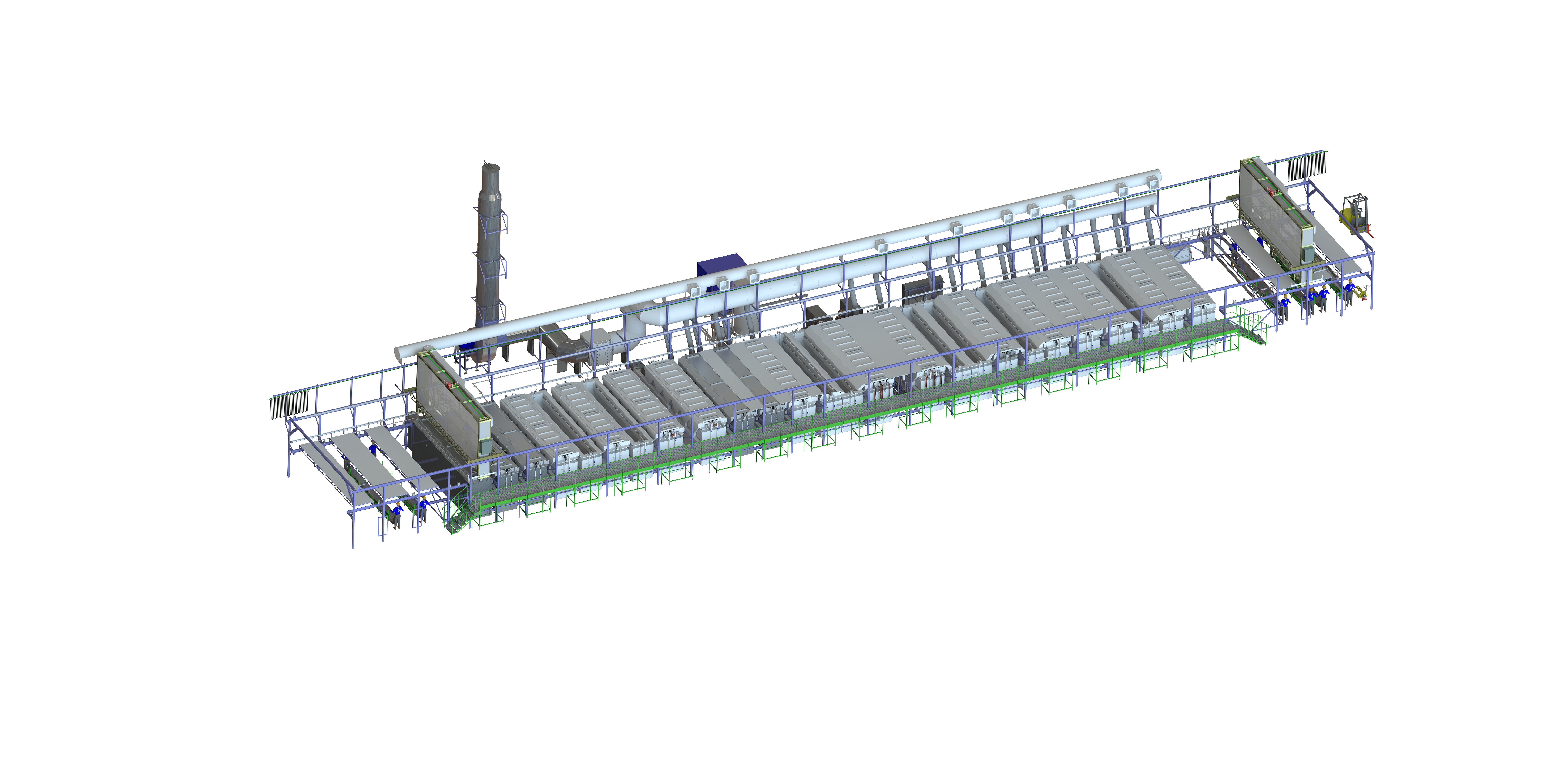
Fourteen positions along the process route, plus the engineering systems layer. Tap a position to open its full description and page through the operations in order.
The process route · scroll horizontally, tap a position for its description
Engineering systems layer
The process equipment in full
The complete scope of the automated line - all 20 positions from the source documentation, with category filters and search.
System map
20 positions
Loading station
Receives and positions loaded jigs before processing begins. Synchronises with the hoist and feeds work steadily into the first tank on the line - degreasing.
Synchronised with the hoist
Carrier storage rack
Stores and stages process carriers and jigs within the line area. The design prevents the tooling from distorting and gives fast access on batch changeover, which keeps the line's rhythm intact.
Fast access on batch changeover
Chemical degreasing tank
A chemically resistant polymer tank that strips cutting fluid, oils, polishing compound and other organic contamination from the aluminium surface. Processing runs in an alkaline solution with surfactants added, with compressed-air agitation to improve the wash.
Alkaline solution with surfactants; air agitation
Two-stage rinse tank with hot lower stage
The hot lower stage accelerates removal of surfactants and emulsified contamination; the upper stage is the final rinse, minimising alkali carry-over into the next operation.
Hot lower stage; final upper stage
E6 etching tank
The production stage of alkaline etching: it blends out minor defects such as scratches and tool marks and develops an even matt surface. Used as preparation for anodizing, to improve both appearance and uniformity of the coating.
Alkaline etch solution
Two-stage rinse tank with hot lower stage
Removes residual alkaline etch solution after the E6 operation. The two-stage scheme with a hot rinse lowers residual alkalinity and prevents contamination of the tanks downstream.
Two-stage scheme with hot rinse
Desmutting tank
Removes the dark smut - the products of etching - and restores the characteristic silver lustre of the aluminium. The acid solution used does not attack the base metal, but cleans the micro-relief effectively before anodizing.
Acid solution that does not attack the base metal
Two-stage cold rinse tank
Removes every trace of the desmutting acid. A cold rinse avoids thermal shock and settles the part temperature before anodizing, where the thermal regime is critical.
Cold rinse; temperature stabilisation
GS-process anodizing tank
The process vessel where a dense oxide layer is grown on the aluminium using the GS process. It produces wear- and corrosion-resistant coatings with controlled thickness and a pore structure suited to subsequent colouring and sealing.
Controlled layer thickness and pore structure
Two-stage cold rinse tank
Required to stop the anodizing reaction by washing residual electrolyte off the surface of the parts.
Cold two-stage rinse
Hot rinse tank
An intermediate hot rinse before sealing: it clears residual electrolyte and loosely bound contamination and conditions the coating for the sealing operation that follows.
Elevated water temperature
Sealing tank
Seals the pores of the anodic oxide coating, which is what delivers the specified corrosion resistance.
Raises corrosion resistance
Drying
Thermal drying after sealing removes residual moisture from the pores and the surface, preventing spotting, streaking and secondary contamination before storage or packing.
Removes residual moisture from the pores and the surface
Two-position cooling rack
Lets parts cool safely after drying and settles their temperature before unloading. The two-position design provides buffer storage and evens out the line's rhythm when cycle times differ between batches.
Two positions; buffer storage
Unloading station
Used to take finished parts off the carriers and pass them to store or onward processing. Unloading is ergonomic and safe, with no damage to the coating.
Ergonomic unloading without damaging the coating
Gantry hoist
The automated transport unit that moves jigs between tanks and process positions. It guarantees precise positioning, stays synchronised with the process cycle and removes manual handling, which is what makes coating quality repeatable. Delivered capacity is up to 700 kg against a 500 kg specification.
Precise positioning; synchronised to the cycle; up to 700 kg
Process carrier
The universal carrier jig that holds aluminium parts on the line. Its design gives reliable electrical contact for anodizing, even current distribution, and straightforward loading and unloading without damaging the product.
Reliable electrical contact; even current distribution
Exhaust ventilation system
Local ventilation over the tanks, capturing acid and alkali vapours, mists and other harmful substances at the point of release.
Local exhaust ventilation; lip extraction
Anodizing electrolyte cooling system
Holds the electrolyte in the anodizing tank at its specified temperature.
Electrolyte thermal stabilisation
Industrial PC control console
The central control interface for the line: it displays tank parameters - temperature, current, time - drives the hoists, archives data and raises alarms on any deviation.
Temperature, current, time; data archiving; alarms
Table 1 of the source documentation · 20 of 20 positions
The production layout
As set out in the specification, EVESS engineers took part in preparing the construction design documentation, which carries both the customer's requirements and the specifics of the line.
- Placement of the automated anodizing line, the supporting areas - preparation, quality control, jig and tooling store - and the access routes for people and equipment.
- A single directional process flow: tanks and process positions in sequence, with no opposing or crossing jig movements.
- Maintenance access: minimum clearances around the line of no less than 1.2 m, with access to control panels, rectifiers, pumps and filters to the applicable electrical and industrial safety rules.
- Equipment dimensions and weights carried into the structural calculations for floors and foundations.
- Dedicated areas for the effluent treatment plant and the utility rooms.
From alloy analysis to process regime
A production programme of 370,000 m² a year on three shifts demanded a systematic approach to equipment selection. The task was not only to reach the volume, but to hold anodic coating thickness at 15 ± 3 µm consistently, across products in aluminium and its alloys.
Optical emission analysis was carried out on samples of the alloys to be coated. That made it possible to select equipment matched to the required throughput, and to work the process out in detail: exact regimes for temperature, immersion time and current density, and a verified electrolyte composition. The result is an even, durable anodic layer that meets the service requirements, a shorter production cycle and a lower risk of defects.
Environmental performance was treated as a design requirement in its own right: the solution chemistry and process parameters were selected to reduce emissions and to lighten the load on the treatment plant. The process scheme was reconciled with the effluent treatment system from the outset, so the plant operates within its environmental obligations.
Designing from the product outwards
Process regimes, electrolyte composition and the equipment set on this project were all selected from the optical emission analysis of the customer's actual alloys - not carried over from a standard configuration.
Monitoring the electrolyte and the coating
EVESS specified the laboratory equipment for monitoring electrolyte parameters and assessing the quality of the coated surface. The customer received a specification covering technical characteristics, the parameters to be monitored and methodological guidance on using the instruments within the anodizing process chain.
Electrolyte monitoring
- Concentration
- Acidity
- Contaminant content
Coating inspection
- Coating thickness
- Porosity
- Coating uniformity
The gantry hoist inside its sealed enclosure
One of the defining features of the line is the EVESS-developed gantry hoist, housed inside a sealed enclosure. The enclosure is formed from a PVC membrane on a frame, creating an isolated volume that keeps mists and vapours from the process solutions out of the shop.
Forced exhaust ventilation is run over every process tank, with an open spigot mated to the enclosure. That spigot maintains a stable negative pressure inside and gives an organised path for contaminated air, so no vapour or mist escapes into the shop uncontrolled.
Ventilation and industrial effluent treatment
The effluent treatment plant is covered by the design documentation and the shop layout; the line's process scheme was reconciled with the industrial effluent treatment system.
Air flow
- 1Tank - the source of emissions
- 2Lip extraction / enclosure spigot
- 3Exhaust network
- 4Controlled discharge
Water flow
- 1Rinse waters and concentrates
- 2Segregated effluent collection
- 3Neutralization of acids and alkalis
- 4Removal of metal ions, including aluminium compounds
- 5Removal of suspended solids and organic contamination
- 6Verification against the required discharge limits
Control over every parameter
The control system visualises production and drives every stage of the process cycle automatically. Temperature, current, voltage and immersion time are all monitored; the system drives the hoists, archives the data and raises alarms on deviation.
Pre-loaded recipes for different product types and coatings standardise the operations: the critical parameters are set and held automatically, so the operator supervises and responds to deviations rather than setting regimes by hand. A manual mode covers set-up and service work.
jig route · hoists 1 and 2
Electrolyte temperature
20.4 °C
within setpoint
Current
412 A
within setpoint
Voltage
17.8 V
within setpoint
Immersion time
38:20
within setpoint
A demonstration of the EVESS interface. The values shown are illustrative and are not the parameters of a real process.
Bringing the line into production on site
EVESS carried out full commissioning on the customer's site, from checking individual assemblies through to handing over the working regimes. The work closed with a report recording the established regimes and recommendations for holding anodizing quality steady.
- 01
Verification of process assemblies and systems
- 02
Equipment set-up
- 03
Calibration of the electrochemical parameters: voltage, current density, electrolyte temperature
- 04
Start-up and verification of the control system
- 05
Verification of the process recipes
- 06
Inspection of the first production batches
- 07
Confirmation that the coating meets the applicable standards and the customer's specification
- 08
Operator training: operation, safety, parameter monitoring and identifying deviations
- 09
Report issued and the working regimes handed over
Ongoing process support
Once the line entered production, EVESS specialists continued to provide process support:
Selection of electrolyte compositions and adjustment of regimes to reach the required coating characteristics: thickness, hardness, colour and corrosion resistance.
Advice on selecting and adjusting process recipes, and on adding new modules to the line.
Guidance on rapid bath analysis, process parameter monitoring and what to do when something goes wrong.
Specialist visits to the customer's site where required.
A platform the plant can grow on
Expansion is currently at the study stage.
The architecture of the line was laid out for growth from the beginning: reserved space, cable routes, ventilation runs and service connection points make it possible to add capacity and process modules - extra rinse tanks, and colouring and sealing sections.
Using the infrastructure already in place - services, water treatment, ventilation and the control system - keeps capital cost well below that of building a separate area. Adding metal salt and organic dye colouring would widen the product range without taking more floor space. New tanks integrate into the existing monitoring and control system, so the quality standards and coating requirements carry over unchanged.
What the project delivered
Throughput without bottlenecks
Every part of the line - etch, anodizing and rinse tanks, cascade systems - was reconciled on dimensions, capacity and operating parameters. Precise calculation of throughput and of the complete process route, from degreasing through to finishing, gave the line a single rhythm for three-shift operation against a programme of at least 370,000 m² a year.
Repeatable coating quality
The 15 ± 3 µm anodic layer is held by automatic control of current density, voltage, electrolyte temperature and immersion time. Filtration and thermal stabilisation keep solution composition and temperature inside their limits, while standard process cards standardise the operations and take operator variation out of the result.
Environmental and operational safety
Sealed hoist enclosures and local exhaust ventilation contain vapours and mists at the point of release; the process scheme was reconciled with the industrial effluent treatment system, and the layout allows for the treatment plant - so the operation runs inside the applicable regulations.
Ready to expand
The reserved floor space and service routes make it possible to bring colouring tanks into the running plant: a wider range of coloured finishes with no increase in floor area and no break in the single quality management system.
Photographs from the project
Photographs taken on site: the anodizing line, the gantry hoists, the control system and the finished parts.
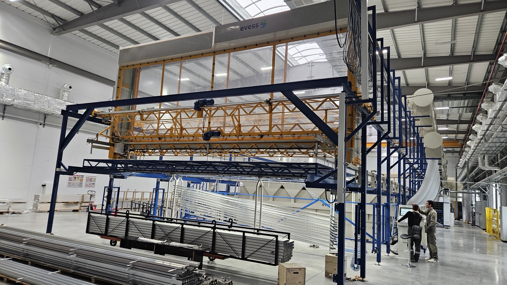
General view of the line in the shop
Page with the arrows or swipe · tap a photo to open it full screen
A walkthrough of the line
Planning a new anodizing plant, or an upgrade to an existing one?
EVESS engineers will review your product range, materials, coating requirements, production programme and available infrastructure, and come back with the optimal line configuration and the engineering systems to go with it.
Discuss the project
We reply within one business day.